At work we get a free packet of bacon (or something else they have heaps of to get rid of) per week, and at Christmas a free ham. So people could self-record their taking of their allocation I built the “Bacon/Ham Machine”. The original one is an Arduino, a 20×4 LCD screen, a MiFare reader/writer to read our door access cards/fobs, and a LED button or two in a box connected to a computer via USB. The smarts were originally handled by a python script but it was re-written in C# .NET in the form of a Windows service. It was first used for recording the ham given out at Christmas. The ham that year was distributed from the factory shop. After that first use it moved onto its Bacon recording use (in the factory shop). The next year the ham was distributed outside (from a chiller truck) and the Bacon/Ham machine was moved outside for the job, connected to an ALIX SBC (running Linux) with power and network cables run out from inside. Obviously that was less than ideal as bacon couldn’t be recorded while ham was. After that a different device was used a couple of years, still with cables running out from inside, and one year just a manual system was used.
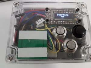
So for Christmas 2016 I decided to make a battery operated WiFi connected portable ham recording device. It operates similarly to the previous devices in that it is fairly dumb device with the smarts running on a proper computer. It just opens a simple TCP connection to a program running on a “proper” computer that tells it what to display and what buttons to light up, and it tells the program the ID of a fob when one is read and when buttons are pushed. I used:
Powering the LED on the switch was interesting as the M0 CPU used can only sink/source a tiny amount of current so I fell back to my old standby, a ULN2003 darlington transistor array IC. As this switches the negative side and the M0 has internal pull-ups on the GPIO inputs this led to quite a messy switch wiring (common negative for the switches and common positive for the LEDs). In retrospect I should have just used some individual transistors for the switch LEDs so I could have switched the positive side, but I was in a bit of hurry. The box was also a bit small for all the stuff I put in it, hence why one of the switches is different as the ones with the LED just wouldn’t fit.
I had some issues with the WiFi. The examples have a delay(10000) after the WiFi.begin() which adds quite a delay to connecting to the WiFi. I don’t like big delays for no apparently reason so I took it out and replaced it with a loop that exited when the module reported that it was connected. This resulted in much quicker connections to the WiFi but the whole thing would only run for a few minutes at most and then it would just lock up/crash requiring the reset button to be pushed. So I went back to the 10sec delay and then it ran fine. I tried lots of combinations of stuff and only the 10sec delay worked, so I stuck with that. The other issue I had was the module wouldn’t connect to our Meru AP320 access points at work. Thankfully it would connect to the AP1020s as those model APs covered the areas it was going to be used in. I don’t know if it was the AP320 itself it didn’t like or the Virtual Port setup. The AP1020 WLAN ESS profile was set as a Virtual Cell instead. I was going to try setting up a standard ESS profile without virtual port on the AP320 and try that but I never got around to it.
I also had issues with reading the buttons. They worked fine without the OLED initialised, but stopped reading properly when the screen was used. In the end I only needed the one button so got one working and left it at that.


